
Key Features
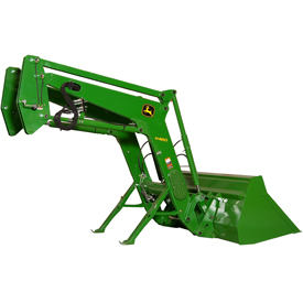
- Superior strength and visibility
- For heavy-duty chores
- Parking stands are integrated on the loader
Features
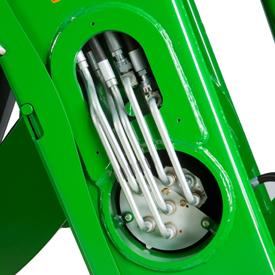
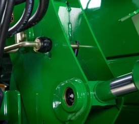
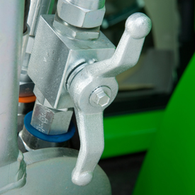
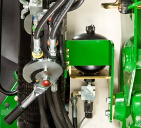
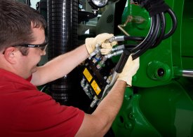 Single-point hydraulic connection (open)
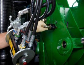
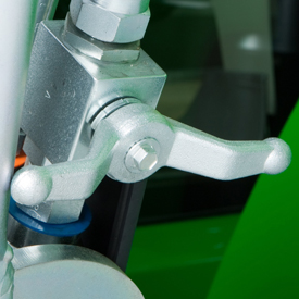
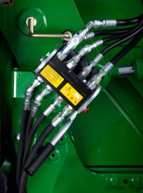 Single-point hydraulic connection (closed)
The H380 Loader features a single-point hydraulic connection that also incorporates the connection point for any electrical needs in base machine. To disconnect the hydraulic connection between the loader and the tractor, it is necessary to relieve the hydraulic system oil pressure on the tractor.
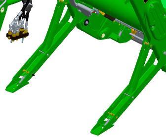
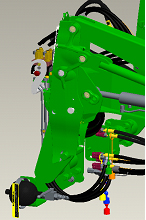
 Concealed oil lines through boom arm
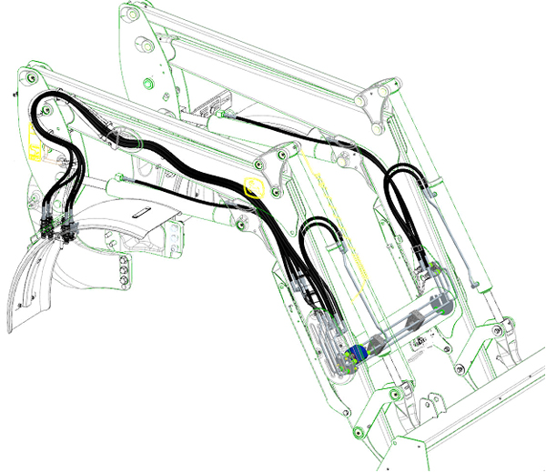
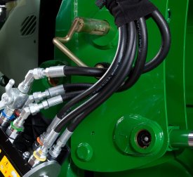
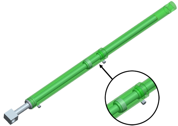
 Oil lines routed through the boom arm
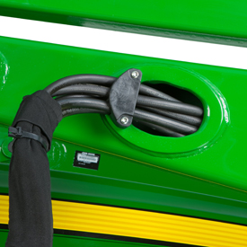
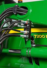
 Oil lines routed through the torque tube
Over time, increased width in tractor hoods have caused issues with available space for running traditional oil lines of a loader along the boom, making them more susceptible to damage.
To improve this situation, the oil lines have been routed through the boom arm and the torque tube, improving line protection and the appearance of the loader.
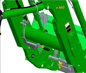
 Parking stands
John Deere loaders are easily removed and reinstalled on tractors without tools. The parking system allows removing or attaching the loader to the tractor in minutes without the need for tools.
To remove or park the loader, apply slight down pressure to the loader boom with the bucket dumped at approximately a 30-degree angle. With the tractor in park, install the parking stands and place the mast pins in the open position.
Removing or parking the loader (7R/H480 Shown)
 Bucket slightly dumped and down pressure (7R/H480 Shown)
 Parking stand in stored position
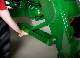 Removing parking stand
 Bucket slightly dumped - Parking stands installed (7R/H480 Shown)
 Mast pin in the closed position
 Rotating mast pin to the open position
Utilizing the boom circuit with the tractor in neutral, rotate the mast forward until the mast has rotated past the pin location on the mounting frame by extending the lift cylinder. Now using the bucket circuit, roll back the bucket until the mast is removed from the pocket and will clear the tires.
 Mast pin in the open position
 Masts rotate forward, then bucket rolled back (7R/H480 Shown)
With the tractor in park, shut the engine off and relieve the hydraulic pressure as indicated for the tractor. Relieve pressure on the single-point hydraulic connection, then disconnect or open the single-point hydraulic connector.
 Relieving the hydraulic pressure
Disconnect/open single-point hydraulic connection
Relieving the hydraulic pressure
Disconnect/open single-point hydraulic connection
Store the loader half of the single-point connector. The tractor is now ready to back away from the loader.
 Storing the hydraulic hoses (7R/H480 Shown)
 Tractor ready to be backed away from loader (7R/H480 Shown)
 Backing away from loader (7R/H480 Shown)
 Parked loader (H480 Shown)
 Hydraulic shut-off valve (open position)
 Hydraulic shut-off valve (closed position)
A hydraulic shut-off valve is included with the H-Series Ag Loaders to ensure the loader does not lower suddenly. For example, this allows the boom to be locked out when someone is required to be located under the loader boom for service work on the tractor. It should not be used for extended periods of time unless an appropriate support stand is also utilized.
 False rod cylinder
Fast bucket cycle times are important to dump the load from the bucket as quickly as possible, (quite often) in order to be as productive as possible, while completing loading operations. The bucket cylinder design can have a major impact on this cycle time, especially for the mechanical self-leveling loaders.
Therefore, all MSL H-Series Loaders utilize false rod bucket cylinders. A false rod cylinder has a smaller displacement of oil requirement on the head end of the cylinder, which allows this cylinder to dump much faster than a normal cylinder.
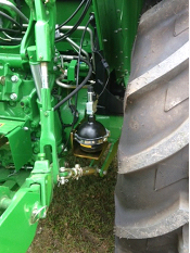
 Nitrogen-charged accumulator and electric valve
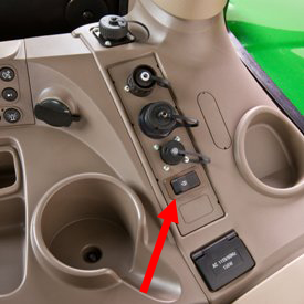 Operator on/off switch
 LSS on H180
 LSS on 5E and 5M
An enhancement to the loader is the suspension system. A great level of loader productivity is achieved with the LSS.
- An accumulator charged with nitrogen and connected to the head-end lift cylinder hose through a T-fitting provides shock absorption
- The cylinders move in and out to allow the boom to float
Performance
- Bales can be transported more efficiently from one end of the field to the other over frozen, hard-packed, or rutted terrain.
NOTE: Check bale-handling capability of tractor before use.
- Pallets can be moved easily without sustaining cargo damage
- Pallets of seed or fertilizer can be carried across a yard without a bag spilling and creating a costly mess
- A properly-ballasted tractor with LSS has increased stability, creating a smoother ride for the operator
Cost of ownership
-
Extended life of loader pins and bushings
-
Less stress on tractor axle
Reasons for turning LSS off include:
- Digging applications - with LSS on, the cylinders retract slightly, losing lifting power
- Holding a grade when blading - with LSS on, it is difficult to hold a constant grade
- Precise pallet and bale handling - with LSS on, the load moves up and down slightly while being positioned
- Parking a loader - with LSS on, when down pressure is applied, the lift cylinders retract slightly, making it more difficult to park
The switch is conveniently located in the operator station to avoid having to exit the tractor seat to manually move the handle on the LSS.
LSS can also be ordered with a manual shutoff. Depending on the tractor/loader model, the accumulator is located in different places. On the 440R, the accumulator is mounted outside the bottom of the mounting frame. On the 5 Series Tractors, the accumulator is mounted near the inside of the rear right wheel. On 6 Series tractors and larger, it is mounted in between the hydraulic connection and the mounting frame.
 6125R Tractor and H340 NSL Loader with RTP
Overview
The RTP option for 6R Tractors and H340, H360, and H380 Loaders provides superior productivity and repeatability during material handling operations. An industry exclusive, RTP allows the operator to store two boom positions and two bucket positions through the use of sensors, the tractor’s CommandCenter™, and controller.
With a simple activation of the momentary detents on the electronic joystick, the loader will return to the preset positions. A complete loading cycle now can be accomplished with four movements of the joystick thus significantly improving productivity. Operator stress is also significantly reduced as there is no need to constantly check the loader height and attachment angle during the operation.
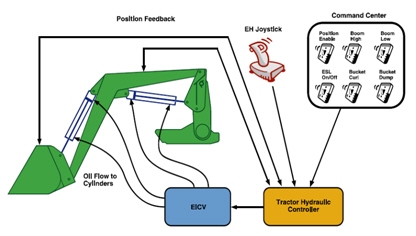 RTP System Overview
The RTP option also incorporates another industry exclusive with the electronic self-leveling (ESL) feature. ESL utilizes the same components as RTP to provide self-leveling capability without the use of mechanical linkages or complex hydraulics.
When the RTP option is installed on a non-self-leveling (NSL) loader, the ESL functionality transforms it into a self-leveling loader. If the a material handling operation does not call for the repeatability of RTP and the self-leveling functionality of ESL, the operator can simply deactivate the system and utilize the loader in the traditional NSL manner.
For operators demanding superior lift capacity and productivity, RTP can be installed on a mechanical self-leveling (MSL) loader as well. While RTP will enhance the repeatability, the ESL feature will improve the leveling accuracy of the MSL loader.
Since the RTP option does not affect the base characteristics of the loader (for example, lift capacity and breakout force), operators need to carefully choose the appropriate loader for their material handling needs. The below chart shows the benefits RTP will offer customers when installing on either a NSL or MSL loader.
| Feature |
Without RTP/ESL |
With RTP/ESL |
||
NSL |
MSL |
NSL |
MSL |
|
| Visibility | Excellent |
Good |
Excellent |
Good |
| Leveling accuracy | None |
Good |
Excellent |
Excellent |
| Rollback/dump angle | Wide range |
Limited range |
Wide range |
Limited range |
| Rollback limitation at full height | No |
Yes |
Yes |
Yes |
| Lift capacity | Good |
Excellent |
Good |
Excellent |
| Boom breakout force | Good |
Excellent |
Good |
Excellent |
| Bucket rollback cycle times | Excellent |
Excellent |
Excellent |
Excellent |
| Bucket dump cycle times | Good |
Excellent |
Good |
Excellent |
| Boom raise/lower cycle times | Excellent |
Excellent |
Excellent |
Excellent |
| Capable of storing two boom and two bucket positions | No |
No |
Yes |
Yes |
| Repeatability | No |
No |
Yes |
Yes |
| Productivity | Fair |
Good |
Excellent |
Excellent |
NOTE: Refer to the sales manual or operator’s manual (OM) for complete list of loader specifications.
Operation
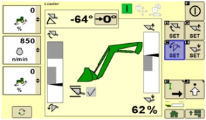 RTP screen within the CommandCenter
The RTP operator interface consists of one single screen within the CommandCenter for simple, straightforward setup and operation. Through this screen, the operator is easily able to activate the system, store two boom and two bucket positions, set the zero position for the attachment, and monitor the boom and bucket positions.
 6R CommandArm™ with electronic joystick
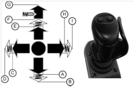 Momentary detents: B, D, F, and I
Once the operator has saved the two boom positions with buttons (G) and (H) and the two bucket positions with (B) and (C) in the CommandCenter, the operator initiates the automatic functions through the use of the electronic joystick’s momentary detents.
Compatibility
RTP is only compatible with 6R Tractors equipped with electronic joysticks and electronic independent control valves (E-ICVs). On the loader side, RTP is compatible with H340s, H360s, and H380s as long as they include the single-point hydraulic connection (single-point connection is included in the 6R Loader ready packages and is the only connection option available for the H380). RTP is not compatible with loader suspension, but it is compatible with both Triple-Link Suspension (TLS™) and cab suspension available on the 6R Tractors.
Calibration
Once the loader components have been installed and the loader is mounted to the 6R Tractor, a calibration must be performed by a dealer service technician. This simple calibration procedure is only required to be performed once unless a sensor or linkage is replaced or the loader is installed onto another 6R equipped with the RTP option.
Key Specs
| Maximum lift height (A) | 4401 mm 173 in. |
| Lift capacity at full height | Measured at pivot (U) 1922 kg 4228 lb |
| Boom breakout force | Measured at pivot (Y) 3594 kg 7907 lb |
| Bucket rollback force capacity | At ground-level line (ZZ) 4838 kgf 10644 lbf |
| Clearance at full height - bucket dumped (C) | 3343 mm 132 in. |
| Dump angle, degrees (E) | 68 degree (angle) |
| Rollback angle, degrees (G) | 47 degree (angle) |
Tractor
| Model | 7430 MFWD |
| Front tire | 16.9R28 |
| Rear tire | 18.4R42 |
| Front axle configuration | |
| Wheelbase | 2685 mm 106 in. |
| Pump capacity | 32 gpm |
| Rated pressure | 2900 psi |
Loader
| Base weight | 1721.9 kg |
| Leveling configuration | |
| Bucket used | 2450 mm 96 in. |
| Bucket weight | 375 kg 825 lb |
| Lift capacity at full height | Measured at pivot (U) 1922 kg 4228 lb Measured at 800 mm ahead of pivot (V) 2094 kg 4607 lb |
| Lift capacity at 59 in. (1500 mm) | Measured at pivot (W) 2895 kg 6369 lb Measured at 800 mm ahead of pivot (X) 2763 kg 6079 lb |
| Boom breakout force | Measured at pivot (Y) 3594 kg 7907 lb Measured at 800 mm ahead of pivot (Z) 3215 kg 7073 lb |
| Bucket rollback force capacity | At maximum height (VV) 2587 kgf 5691 lbf At 59-in. (1500-mm) lift height (XX) 4879 kgf 10734 lbf At ground-level line (ZZ) 4838 kgf 10644 lbf |
| Dimensions | Maximum lift height (A) 4401 mm 173 in. At full height - bucket level(B) 4193 mm 165 in. At full height - bucket dumped (C) 3343 mm 132 in. |
| Overall length (I+F), ft (m) | |
| Overall height in carry position (J) | |
| Digging depth (H) | 252 mm 10 in. |
| Reach | At maximum height (D) 1045 mm 41 in. At ground level - bucket level (F) 2695 mm 106 in. |
| Bucket angle | Dump angle, degrees (E) 68 degree (angle) Rollback angle, degrees (G) 47 degree (angle) Dump angle, ground 91 degree (angle) |
| Cycle times | Loader raise, seconds 3.93 seconds Loader lower, seconds 2.47 seconds Bucket dump, seconds 1.72 seconds Bucket rollback, seconds 1.72 seconds |
Additional information
| Date collected |

